Research Intern in Autonomous Embedded Systems
- Period
- Apr – Sep 2022 · 6 mos
- Organisation
 Nokia Bell Labs
- Role
- Embedded autonomous system designer & developer (fixed-term trainee)
- Location
- Nokia Bell Labs Budapest (Skypark)Bókay János utca 36-42, 1083 Budapest, Hungary
- Posted
Designed, built and programmed Raspberry Pi–based autonomous robot cars in C++ to study cooperative multi-agent driving on a down-scaled test track. The core was 9-axis IMU sensor fusion with a self-correcting heading controller for stable line following, and a compact V2V message protocol for sharing vehicle state across the fleet.
- Own project, end to end: mechanics, electronics, software
- 9-axis IMU sensor fusion (Madgwick AHRS) with magnetometer calibration
- Self-correcting heading controller for stable line following
- Compact CAM/DENM-style messages for sharing vehicle state
- Collision-free crossing of intersecting routes by a cooperating fleet
During a six-month fixed-term contract at Nokia Bell Labs in Budapest I owned a project on small autonomous cars that drive together. The goal was to evaluate self-driving behaviour in a real but down-scaled cyber-physical environment, where vehicles share their state and coordinate instead of reacting to each other blindly. The first part of the work also counted as my MSc Project Laboratory 1 at BME's Department of Automation and Applied Informatics, supervised by Dr. Hassan Charaf.
The work had two halves: making a single two-axle, rear-wheel-drive car execute its manoeuvres reliably, and then letting a fleet of them share one surface with crossing routes, without collisions.
The track
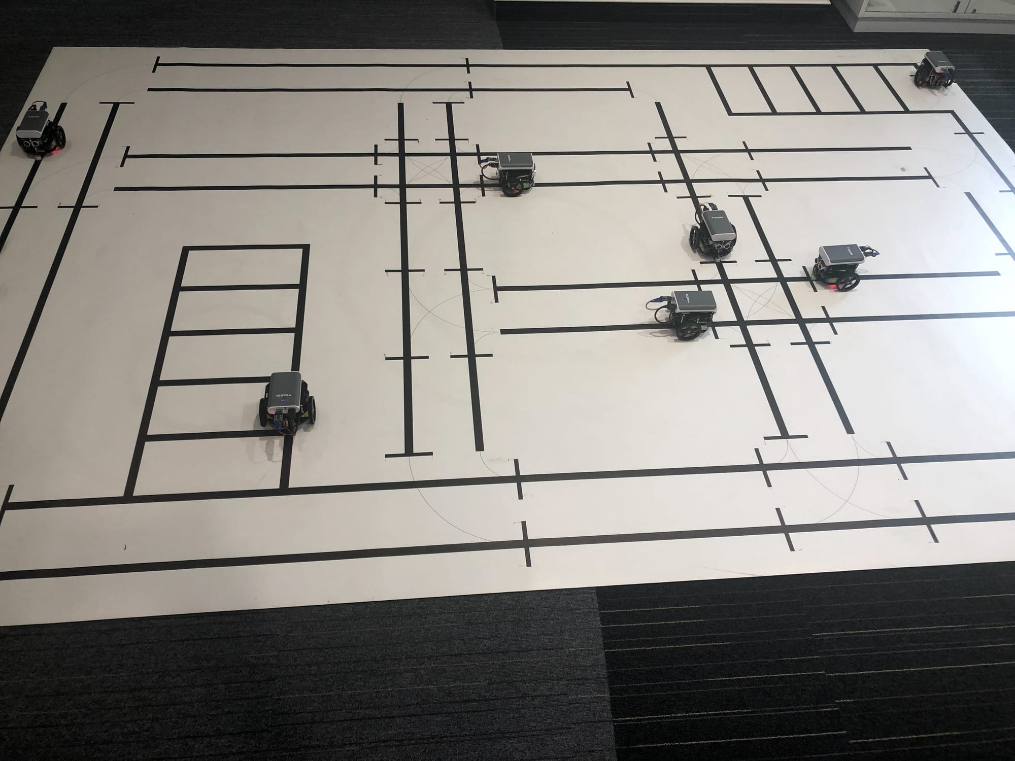
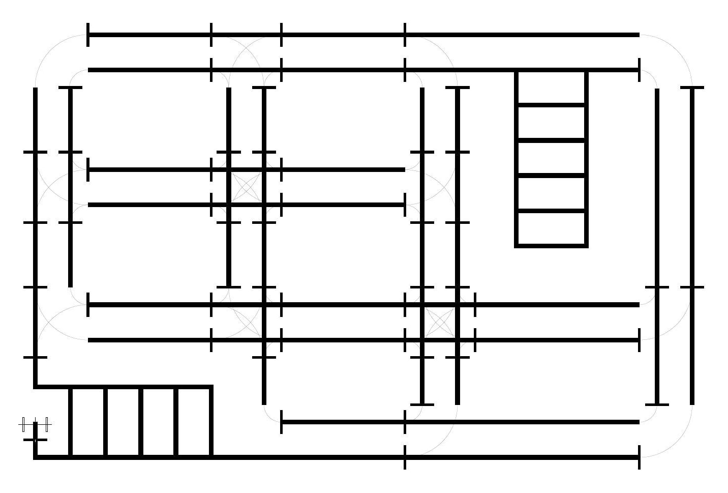
The cars drive on a fixed track printed on a 3 × 2 m mat, following black lines that represent lanes. Every car has the whole route network in memory, with each segment's length known to the millimetre, so it knows how long and how fast to drive and where it is within the current segment. A perpendicular end mark closes each segment: the optical sensors detect it and the car resynchronises its estimated position. Based on the next segment the car picks a manoeuvre: straight ahead, a wide curve, a tight curve or a 90° turn.
The vehicles
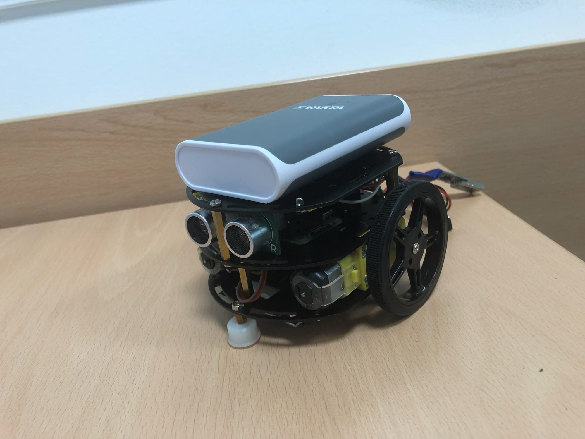
Each car is built around a Raspberry Pi Zero W (40 GPIO pins, 512 MB RAM, Wi-Fi and Bluetooth), runs on a power bank and is programmed in C++. Two motors drive the rear wheels through a DRV8835 driver using PWM, and two LEDs act as indicators and as emergency blinkers, for example when a car is lifted off the ground. Alongside the software I assembled more cars to grow the fleet for testing.
| Component | Interface | What it does |
|---|---|---|
| US-100 ultrasonic rangefinder | UART | Obstacles within a ±15° cone, 2 to 450 cm, 0.3 cm ±1% accuracy |
| NXP 9-DOF IMU (gyroscope, accelerometer, magnetometer) | I²C | Orientation and acceleration in three dimensions, loss of stability |
| 5 × TCRT5000 reflective optical sensors | GPIO | Line following under the chassis, with adjustable sensitivity |
| 2 × EE-SX67 photo-interrupters + 20-slot encoder discs | GPIO | Wheel rotation at 40 state changes per revolution, for calibrating the two motors |
| On-board Wi-Fi | UDP, TCP | Sharing state with other vehicles and receiving remote commands |
Software architecture
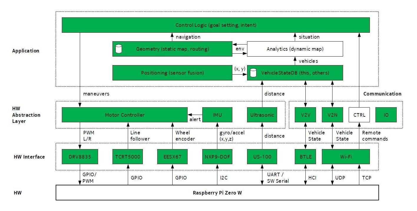
The software is split into three layers. The application layer holds the control logic that sets goals and makes the decisions, a vehicle state database for the car's own state and everyone else's, and a geometry component that stores the track as vectors and plans the shortest route. The hardware abstraction layer hides the sensor and driver specifics: its motor controller turns a manoeuvre into wheel speeds, corrects using the line sensors and the gyroscope, and reports when the manoeuvre is done. The hardware interface reads and writes the GPIO pins. I reworked the manoeuvre execution so that it scales: each manoeuvre type is configured separately, including its edge cases (such as leaving the line) and which sensors it relies on.
Holding a straight line
With the two axles calibrated, the cars could already drive fairly straight, but tests showed them wobbling between the edges of the line. Five binary line sensors are too coarse for small corrections: the path got longer, the corrections grew in frequency and angle, and eventually the car lost the line altogether. The fix was to make fine, continuous corrections from the IMU, with the optical sensors as a backstop.
- Gyroscope only. Averaging the angular rate over quarter-second windows and integrating it was cheap and nearly good enough, but drifted over longer runs because of noise and residual bias.
- 9-axis sensor fusion. I switched to an AHRS (attitude and heading reference system) filter that combines gyroscope, accelerometer and magnetometer. I chose Madgwick over Mahony because it is more accurate on noisy data, and the controller has to react to rotations of just 0.3 to 0.5°. Starting from an open-source C++ implementation, I remapped the sensor axes, converted the units, wrote the missing hard-iron and soft-iron magnetometer calibration, seeded the filter with an initial orientation from the accelerometer and magnetometer, tuned it (100 Hz sampling, gain 0.4) and converted its quaternions to Euler angles.
- A self-correcting heading controller. The car steers towards a reference angle parallel to the line by speeding up one wheel and slowing the other. Nobody knows that angle exactly, and the fused heading still drifts a little through turns, so the car refines it as it drives. When it slips off the line it notes how much of the segment the current angle carried it, and when the line sensors bring it back it notes its heading. The new reference lies between the two, pulled towards the old one in proportion to how well it did. The correction grows linearly with the error up to 2° and with its square root beyond that, so large errors do not cause overcorrection, and it shrinks as speed grows. The loop runs 80 times a second.
This proved very effective. Even when a car came out of a turn at the wrong angle, it found and held the right heading after at most two or three reference updates. Stabilising the turns themselves was the next step, and with absolute orientation available it was no longer a hard one.
Sharing state
The point of the fleet is cooperation: once cars know each other's position, speed and heading, they can perform collaborative manoeuvres, such as crossing an intersection without stopping by matching their speeds. Each sensor feeds that shared picture:
- The ultrasonic sensor catches objects that do not broadcast their state. The car measures the distance and tells the others where the obstacle is, so they can reroute.
- The accelerometer and line sensors notice when a car becomes unstable, tips over or leaves the track, so it can warn the others away from that segment.
- The wheel encoders measure the distance driven within a segment, giving a precise position to share.
The first plan was Bluetooth broadcast, but the many read and write operations would have overloaded the already busy Pi Zeros. Instead, messages go over Wi-Fi through a relay server that only filters and forwards them, emulating direct V2V communication. It controls nothing: the cars still decide on their own. A central controller was planned as a later phase, so that the two approaches could be compared.
The two message types are modelled on those of intelligent transport systems (ITS):
| Message | Sent when | Contents |
|---|---|---|
| CAM (Cooperative Awareness Message), 16 bytes | the car's state changes | Sender, current and destination segment, position within the segment (0 to 255), speed, distance to the object in front (mm), sequence number, round-trip time |
| DENM (Decentralized Environmental Notification Message) | a car is stuck, off the track or overturned | Sender, affected segment and its new status (e.g. blocked, cars waiting), position within the segment, sequence number, round-trip time |
Every car keeps a table of the other vehicles' latest states, keyed by sender, and tracks which cars are on which segment, so on entering a segment it knows whom to expect there and where. Since every car loads the full track at start-up, a DENM simply updates the status of the segment it names.
Looking back
This was my first hands-on experience of how much of autonomy is about interaction between agents, not individual control loops. My PhD comes back to the same idea at sea, where the COLREGS define how vessels must interact.
Gallery